3D-AXI Technology

Saki's proprietary "Planar CT" technology is the key to our systems’ unrivalled inspection speed and precision

Leading manufacturers worldwide trust our 3D-AXI systems to ensure the quality of semiconductors, power modules, and PCBs.

Advanced technologies demand 3D CT X-ray inspection

The trend among today’s smartphones is just one example, typifying the move towards smaller, thinner, and more sophisticated electronic products. In turn, this is driving electrical components and semiconductor packages to become more highly miniaturized, more complex, and more densely spaced. Given these external, visible, changes, the adoption of flip-chip ball-grid arrays (FCBGAs), land-grid arrays (LGAs), package-on-package (PoP), and wafer-level packages (WLPs) on PCBs is becoming more prevalent, requiring inspection at a deeper level.

01

Who needs X-ray inspection?

Visual inspection is often insufficient for verifying solder joints of traditional components. X-ray inspection is required as an alternative inspection method.
3D CT X-ray inspection is essential to detect voids and head-in-pillow (HiP) defects in solder joints. There is growing market demand for these capabilities.
In addition, increased global competition has pushed the demands for high-quality products even further, driving the need for full 3D CT X-ray inline inspection.

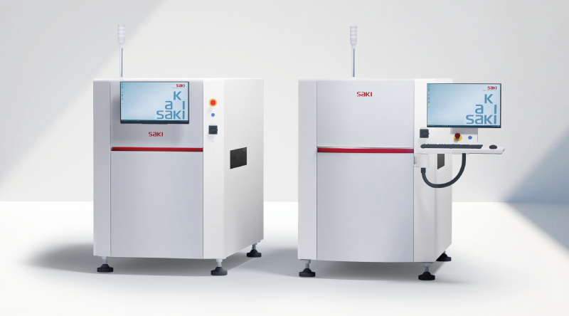
The Saki 3Xi Series 3D-CT Automated X-ray Inspection System

01

Conventional X-ray inspection techniques

There are many x-ray inspection techniques, such as laminography, tomosynthesis, and oblique CT.
All have achieved only limited success in inline volume production, typically imposing a trade-off between cycle time, inspection capabilities, and accuracy.
Saki’s Planar CT technology (Fig.1) has high potential to break through this trade-off.

02

Saki's planar CT technology

Planar CT technology requires fewer projections to acquire the high-definition CT images of planar objects that are needed to perform high-precision inspection. The key challenge is to handle the heavy computational workload. BY developing advanced techniques to accelerate arithmetic processing, Saki has become the first manufacturer to deliver an inline Planar CT solution for X-ray inspection of PCBs. The 3Xi series X-ray inspection machine leverages Saki’s original CT computation software to realize high-speed, high-precision inspection.

Fig.1  Concept of Planar CT technology

03

Comparison between Saki's Planar CT technology and tomosynthesis

The tomogram acquired by Saki’s Planar CT technology shows much higher definition than images acquired through conventional tomosynthesis.

Fig.  Comparison between the images taken by Saki's Planar CT image (Top) and tomosynthesis (Bottom)

04

Flexible configurations for diverse needs

In addition to a closed X-ray tube (110kv) for printed circuit boards, a high-power (180kv) X-ray source option is available for semiconductor devices and high-power modules to meet diverse market demands.

Proprietary Hardware

01

Saki’s unique rigid gantry structure maximizes repeatability of high-definition inspection.

The platform hardware must have high positioning accuracy and a rigid structure to enable consistently accurate, advanced inline inspection, operating for long periods in high-volume production.
The linear motor drives the stage directly to ensure stable positioning accuracy.
In addition, a linear scale on the Z axis of X-ray tube ensures high reproducibility even when the resolution is considerably changed according to the field of view.

Proprietary Software

01

Saki’s Full-Memory Technology ensures ease of use and supports advanced functionality

The unique rigid gantry structure and warpage adjustment, which leverage our expertise in 2D-AOI, combine to acquire seamless 3D images of whole substrates, which are then stored in the memory. This 3D full-screen storing function serves also for traceability.

02

Precision inspection using slices of images recreated by the CT reconstruction operation

3D inspection is performed using slices of images acquired by CT reconstruction operation for inspection. As mentioned above, the challenge when reconstructing CT images for 3D inspection is the heavy computation required, which typically demands high-speed processing.
Our unique solution realizes high-speed 3D inspection suitable for high-volume inline production, producing high-quality images for all types of components.
For example, when inspecting the solder joints of gull-wing leads, our system accurately reproduces the fillet shape. To detect defects such as poor wetting, PASS or FAIL can be classified using the back-fillet position, height, and angle information.

Fig.   3D depiction of solder fillet

03

Evolution of X-ray inspection

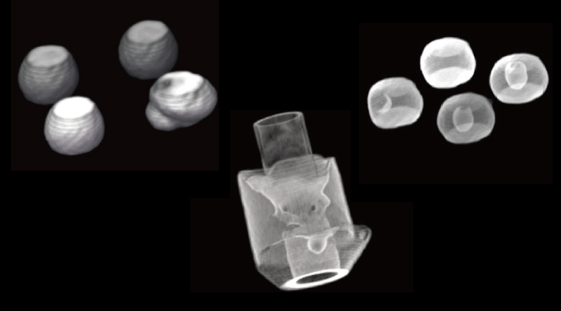
High-definition 3D inspection using slices of images is the most reliable way to detect very small voids (Fig.2) that can occur anywhere in the object. Head-in-pillow defects (Fig.3) occurring in solder balls are difficult to detect using conventional 3D inspection, because they have varied defect shapes. However, shape inspection using Saki's unique algorithm and high-definition 3D images significantly improves inspection capability.

Fig.2  Void in solder balls

Fig.3  HiP in solder balls

04

Compliant with IPC standards

According to IPC standard (Class3), the de facto standard of today’s electronics industry, the height of solder wetting of the gull wing back fillet is defined as the criteria for PASS or FAIL. Demand for back fillet inspection based on the IPC standard is set to increase in the electronics market.
The IPC standard defines many other PASS/FAIL criteria that require accurate assessment of solder shape and volume, such as filling of through-holes (Fig.4) and the characteristics of flip-chip micro-bumps as well as solder joints of Package on Package (PoP) assemblies and power modules.

Fig.4  Through-hole solder

Click here for
the brochures download form