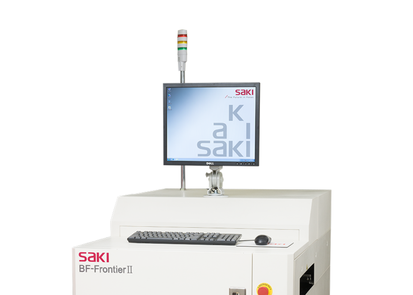
2D Automated Optical Inspection
Systems
2D-AOI
The 2D-AOI is a high-speed, high-precision 2D visual inspection device that supports multiple inspection processes, such as SMT, and through-hole processes. The extremely durable hardware design guarantees a more stable inspection quality than traditional visual inspection and contributes to significant labor savings at production sites.
Simultaneous full-board imaging for high-speed inspection
High-speed inspection is achieved through the simultaneous imaging of the entire PCB, utilizing Saki’s unique line scanning technology. Images of the entire board are rapidly acquired through batch imaging using a line sensor camera – takt time is unaffected by either the number of parts or mounting status.
Line Scanning Technology
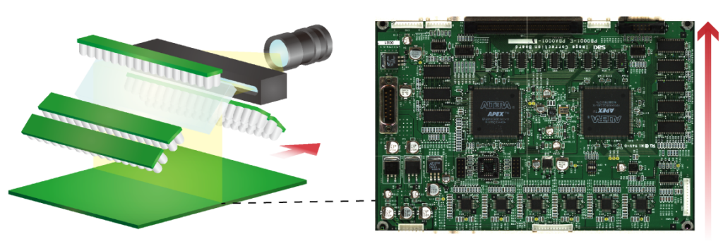
Inspection reliability is improved with hardware specifically designed for high-speed, high-precision imaging, that utilizes Saki’s unique lighting technology for shadow-free image capture.
Hardware design that guarantees high inspection quality for an extended lifetime
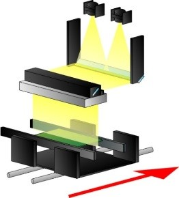
The stable, uniaxial hardware design ensures low vibration and high durability, while a compact housing design contributes to improved area productivity.
Uniaxial Hardware
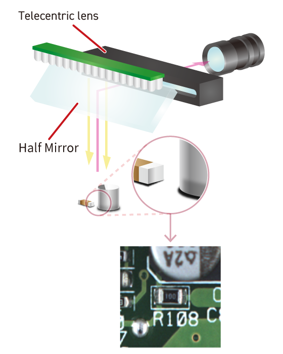
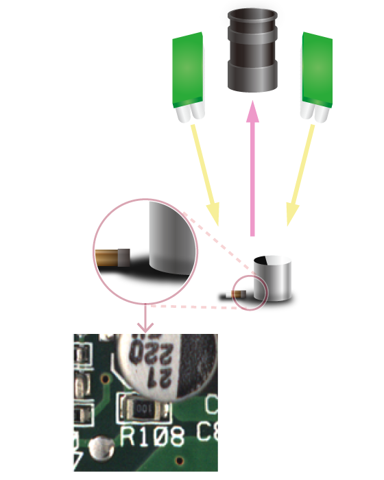
Coaxial top light for shadow-free image acquisition
A coaxial top light illuminates from directly above each inspected component at all positions on the board, capturing angular objects, such as solder surfaces, without being affected by adjacent components.
Coaxial Top Light
Ring Light
System flexibility allows for a range of inspection criteria including simultaneous double-sided inspection, THT solder inspection, and full board inspection.
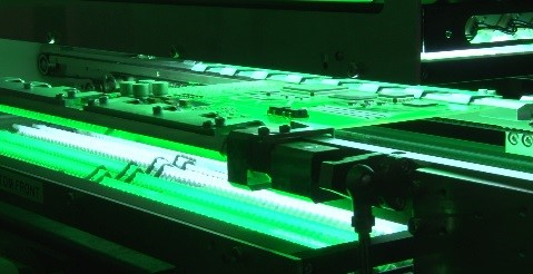
Simultaneous Double-Sided Scanning
The 2D-AOI inspects both the mounting surface and soldering surface of through-hole components at the same time.
Since no reversing machine is required, damage to the board from reversing is prevented, equipment investment efficiency is improved, and area productivity increased by shortening line length.
Simultaneous double-sided scanning
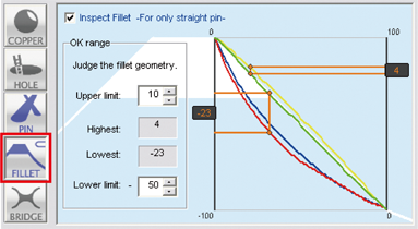
Solder inspection of through-hole components
Saki’s unique lighting technology enables analysis of solder meniscus and pin presence, allowing for the following defects to be simultaneously inspected:
- Copper exposure
- Excessive solder
- Pin presence
- Insufficient solder
- Blow holes
- Solder bridges

Through-hole solder image
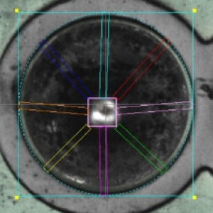
Through-hole solder inspection screen
Full board Extra Component Detection (ECD) ensures that fallen objects and surplus parts are not overlooked
2D-AOI applies Extra Component Detection (ECD) on the entire board surface.
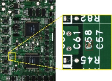
ECD compares a non-defective statistical image with the newly scanned image allowing for the automatic detection of defects such as solder balls and foreign objects.
This process also detects additional defects such as unexpected surplus parts and dust inside the board.
ECD NG Images
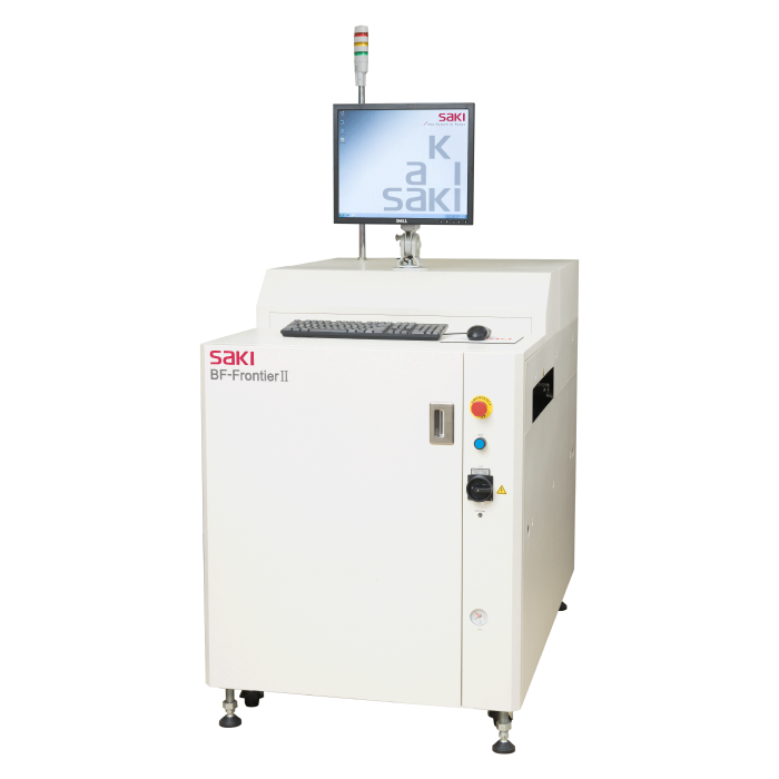
Complete Lineup Suitable for SMT or Back-End Processes
BF-FrontierⅡ
- Inline AOI
- Large size PCBs
- Resolution 18μm
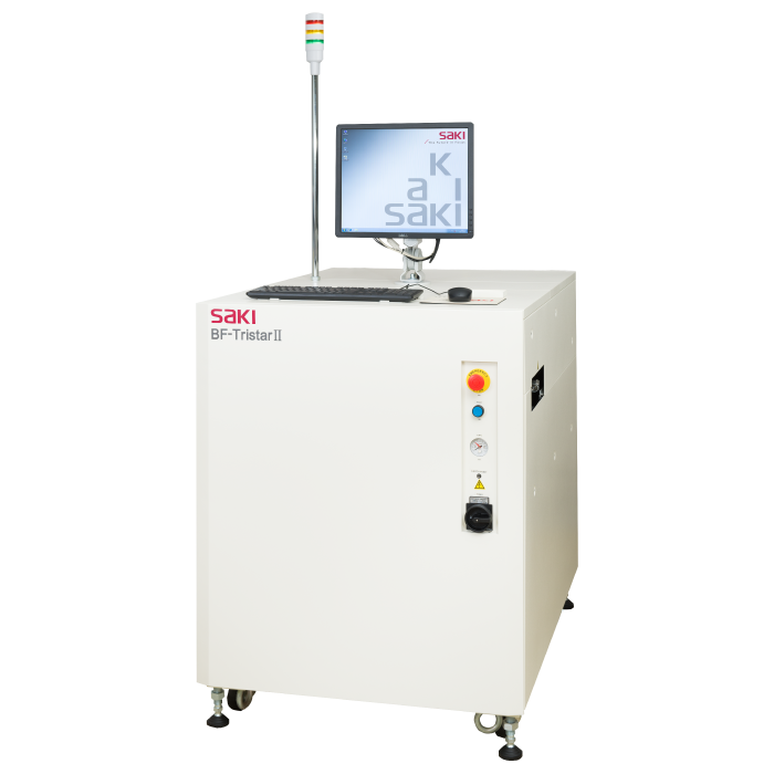
BF-TristarⅡ
- Inline AOI
- Simultaneous double-sided inspection
- Resolution 10μm
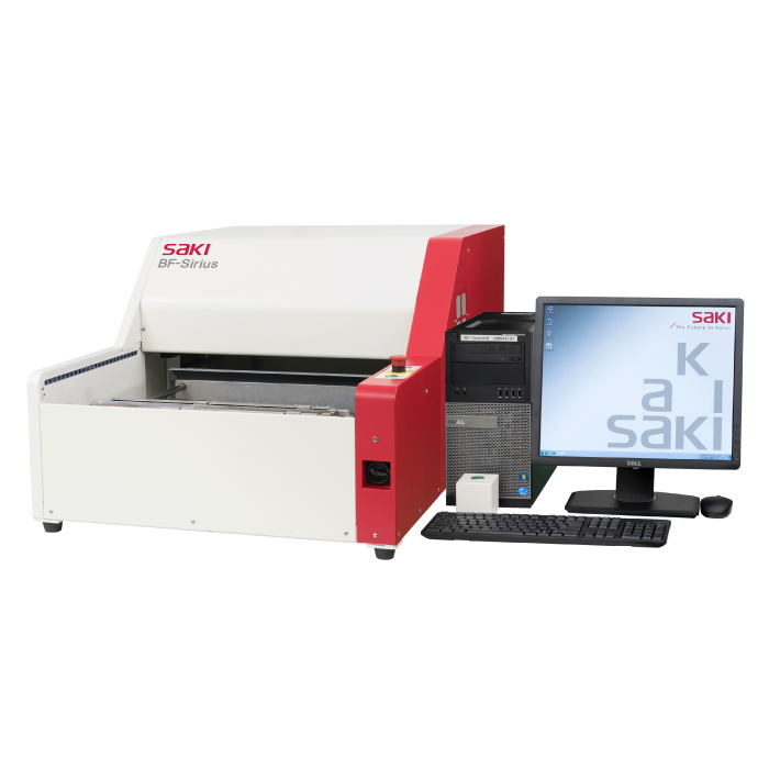
BF-Sirius
- Benchtop
- Large size PCBs
- Resolution 18μm
BF-Comet18
- Benchtop
- Medium size PCBs
- Resolution 18μm
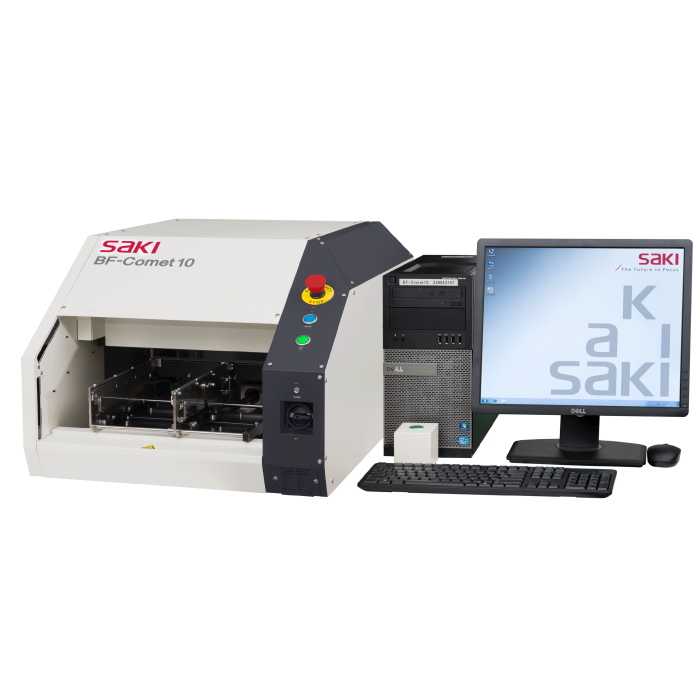
Specification
| Model | BF-FrontierⅡ | BF-TristarⅡ | BF-Sirius | BF-Comet18 |
|---|---|---|---|---|
| Installation type | Inline | Inline | Benchtop | Benchtop |
| Size (W)×(D)×(H)mm (in.) | 850 x 1340 x 1230 (33.5 x 52.8 x 48.4) | 850 x 1295 x 1130 (33.5 x 51 x 45.5) | 800 x 1280 x 600 (31.5 x 50.4 x 23.6) | 580 x 850 x 452 (22.8 x 33.5 x 17.8) |
| Resolution | 18μm | 10μm | 18μm | 18μm |
| PCB Clearance | Top: 40mm (1.57 in.) Bottom: 40mm (1.57 in.) | Top: 30mm (1.18 in.) Bottom: 30mm (1.18 in.) | Top: 40mm (1.57 in.) Bottom: 60mm (2.36 in.) | Top: 40mm (1.57 in.) Bottom: 60mm (2.36 in.) |
| Electric Power Requirement | Single-phase ~ 100-120/200-240V +/-10%, 50/60Hz | |||
| PCB Size (W)×(L)mm (in.) | 50 x 60 – 460 x 500 (2 x 2.4 – 18 x 20) | 50 x 60 – 250 x 330 (2 x 2.4 – 10 x 13) | 50 x 50 – 460 x 500 (2 x 2 – 18 x 20) | 50 x 50 – 250 x 330 (2 x 2 – 10 x 13) |
| Model | BF-FrontierⅡ | BF-TristarⅡ |
|---|---|---|
| Installation type | Inline | |
| Size (W)×(D)×(H)mm (in.) | 850 x 1340 x 1230 (33.5 x 52.8 x 48.4) | 850 x 1295 x 1130 (33.5 x 51 x 45.5) |
| Resolution | 18μm | 10μm |
| PCB Clearance | Top: 40mm (1.57 in.) Bottom: 40mm (1.57 in.) | Top: 30mm (1.18 in.) Bottom: 30mm (1.18 in.) |
| Electric Power Requirement | Single-phase ~ 100-120/200-240V +/-10%, 50/60Hz | |
| PCB Size (W)×(L)mm (in.) | 50 x 60 – 460 x 500 (2 x 2.4 – 18 x 20) | 50 x 60 – 250 x 330 (2 x 2.4 – 10 x 13) |
| Model | BF-Sirius | BF-Comet18 |
|---|---|---|
| Installation type | Benchtop | |
| Size (W)×(D)×(H)mm (in.) | 800 x 1280 x 600 (31.5 x 50.4 x 23.6) | 580 x 850 x 452 (22.8 x 33.5 x 17.8) |
| Resolution | 18μm | 18μm |
| PCB Clearance | Top: 40mm (1.57 in.) Bottom: 60mm (2.36 in.) | Top: 40mm (1.57 in.) Bottom: 60mm (2.36 in.) |
| Electric Power Requirement | Single-phase ~ 100-120/200-240V +/-10%, 50/60Hz | |
| PCB Size (W)×(L)mm (in.) | 50 x 50 – 460 x 500 (2 x 2 – 18 x 20) | 50 x 50 – 250 x 330 (2 x 2 – 10 x 13) |
Related Solutions
3D-SPI
3D Solder Paste
Inspection Machine
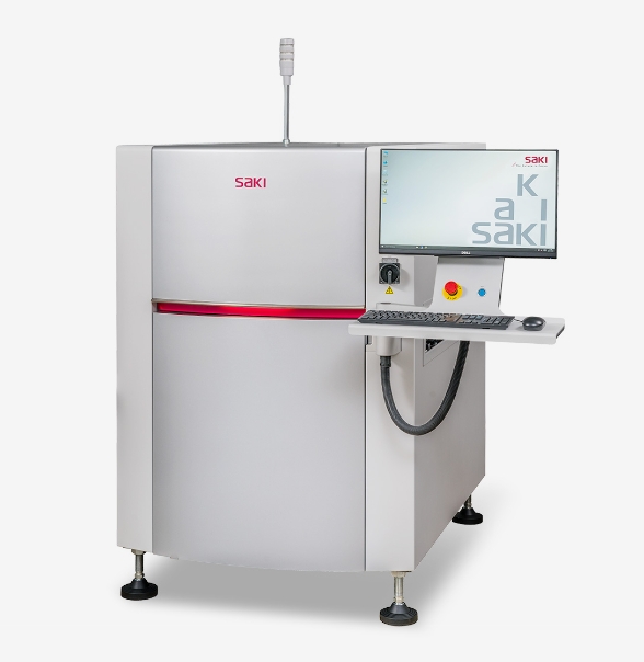
3D-AOI
3D Automated Optical Inspection Systems
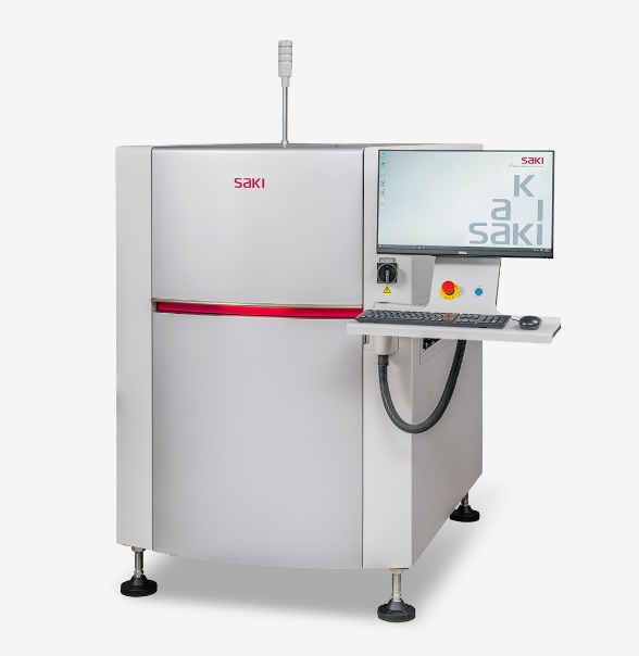
3D-CT AXI
Inline 3D-CT Automated
X-ray Inspection Systems
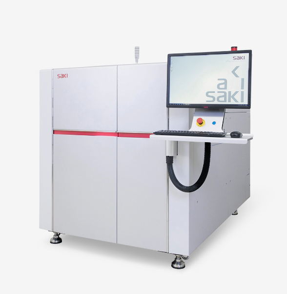
Bottom Side-AOI
Inline Bottom-side 2D Automated
Optical Inspection Systems


